Back in 2018 we installed an Alton electric starter on editor Hall’s Norton Commando. This time around we’re installing the other easily sourced electric starter kit, from Colorado Norton Works. As you can see from the photo above, this is a comprehensive kit that includes a belt drive conversion in addition to the starter. Like the Alton, this kit requires you to replace the inner chain case. The CNW starter requires you to remove the stock ham can air cleaner, as the starter motor takes up some of that space. Fortunately they also sell the K&N compact air cleaner that does fit with the starter. There’s rumor of a smaller stock looking air cleaner in the works from CNW. We’ll look at that when it comes out. Sometimes belt drives change the primary ratio, but this kit barely changes it, from 2.19 to 2.188. The included instructions are comprehensive, follow them and you’ll do fine. If your battery has a few years on it, replace it, preferably with an AGM battery, the largest that will fit in your battery space. We sourced a DEKA ETX16L from our local battery store.
— Keith Fellenstein
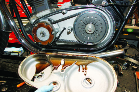
1. Begin by disconnecting the battery. Find the two wires running from the alternator to the wiring harness and unhook them. Disconnect the wires running to the rear brake switch and remove the rear brake pedal. Remove the center bolt from the outer chain case and drain the primary case. Remove the primary cover.
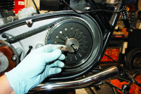
2. Remove the clutch-adjusting nut and clutch rod.
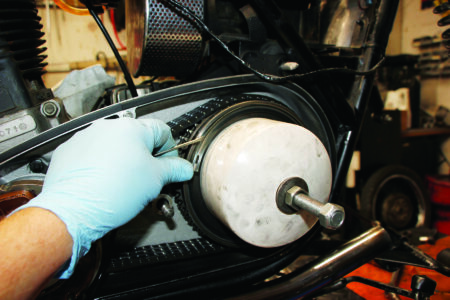
3. Using a clutch spring compressor, tension the spring so you can remove the retaining clip. Remove the clutch pressure plate and clutch plate pack. You can reuse your friction plates if they are not too worn. Ours had worn spline teeth so we purchased new Barnett friction plates.
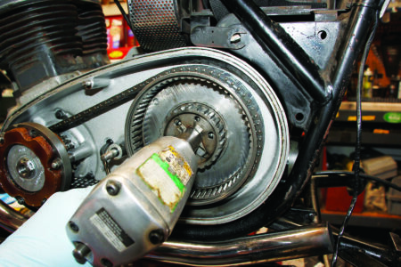
4. Bend back the lock tabs on the clutch hub nut retainer and remove the clutch hub nut with an impact driver. Remove the alternator rotor nut also. Remove the alternator nuts and place the alternator on top of the chain case while you remove the front sprocket and clutch wheel. Disengage the sprocket and chain wheel from the chain. Take the alternator in one hand and slide the chain over it and off, then hang the alternator off the center stud.
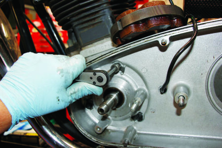
5. Bend back the locking tabs and remove the three bolts holding the primary case to the engine. We’ve placed the alternator back on top of the inner primary while we do this.
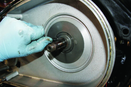
6. Pry the old clutch basket retaining clip out of its groove using your pointed tool of choice. You’re not going to reuse this, so there’s no need to be gentle. Once this clip is out and the three bolts holding the case to the engine are removed, place the alternator back in the case and remove all as a unit. If your Norton wet sumps (like mine), be prepared to replace the lowest screw back in the engine to stop the leak, or place a pan under to catch the oil.
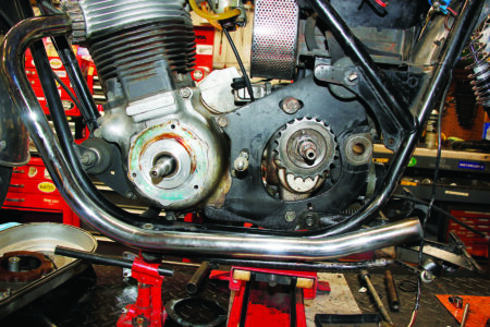
7. Here’s the machine minus the primary case. Inspect the primary sprocket and replace it if it shows signs of wear. You might also want to go up or down a tooth to change bike performance. The swing arm is off of this bike for bushing and pin replacement. I think the British say “In for a penny, in for a pound” or in this case many Pounds. The result should be a better handling bike.
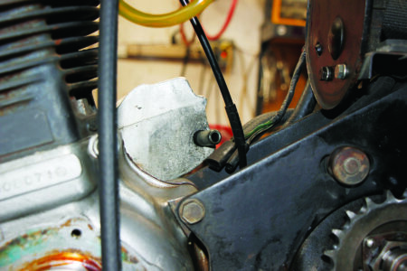
8. Back to the current task. As mentioned, the ham can has to be removed. Once that is out of the way, you have easier access to the breather stub off the back of the timing case. Unscrew it. CNW has provided a slightly shorter one that won’t foul the starter motor. Replace the stock pipe with the supplied shorter pipe.
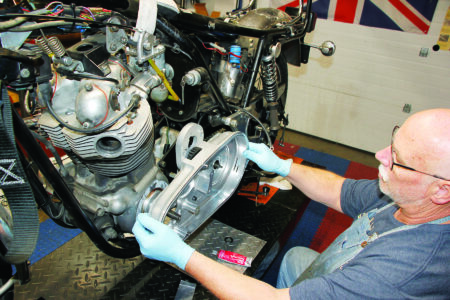
9. Place the new inner chaincase in place, along with the new gasket. Install and finger tighten at least two of the supplied screws that hold the case in place. This is so you can measure the gap between the cover stud and the back of the chaincase. You’ll fill the gap with a combination of the supplied shims.
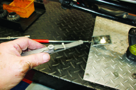
10. I used a mirror to see up under the case to show the gap, and then used feeler gauges to measure that gap. I also used a zip tie to hold the feeler gauges together to get the correct measurement.
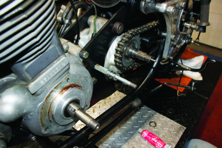
11. Once you have the correct measurement, select shims to fill that void. You can then attach the inner case and bolt it into place. I like to seal the threads on the bolts with a little (very little) RTV silicone. Tighten down the bolts and bend over the tabs on the locking plates.
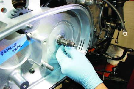
12. Carefully spread the new clutch circlip and push it into place on the mainshaft of the gearbox. The supplied circlip is designed to be used with snap ring pliers so you can spread it just enough to get it started on the mainshaft. It will click into place when home in the slot cut for it. Next you can place the backing washer over the circlip.
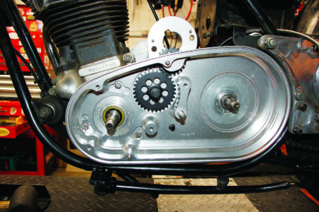
13. Remove the blue painter’s tape covering the bearing. Take the intermediate gear assembly and determine which end fits that bearing and press it into place in the inner case. Carefully remove the washer and gear from the shaft end projecting out from the case. Take note of the orientation of the thrust washer on the end of the shaft. Later when you assemble it back to the shaft you will need to be sure the shoulder of the washer is facing you.
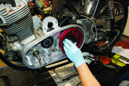
14. Assemble the clutch basket over the mainshaft splines and push it home against the retaining washer. Spin it by hand listening for any contact between the basket and the inner chaincase. If there is interference, you will need to add shims until there isn’t.
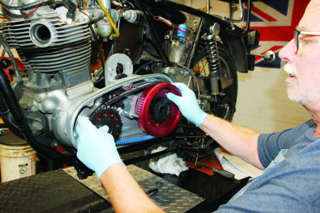
15. Fit the woodruff key into the crankshaft. Taking the belt, front pulley and clutch basket as a unit, fit the belt drive assembly onto the crankshaft and gearbox mainshaft.
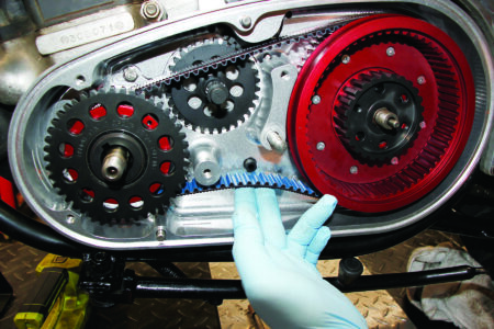
16. Adjust the belt tension using the gearbox adjuster until the bottom run of the belt can be deflected up to the bottom of the alternator grommet. In this case, a little too loose is better than a little too tight. Once you have the setup to your liking, assemble the intermediate gear on the splines, meshing it with the gear on the crankshaft, and place the thrust washer over the end of the intermediate shaft, with the shoulder facing you.
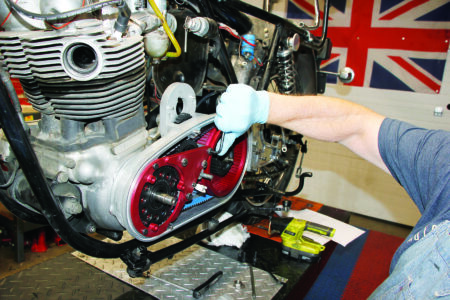
17. Remove the painter’s tape holding the bearing in the alternator carrier and bolt the alternator carrier to the inner case using the supplied bolts and a little blue Loctite. Test the assembly by spinning the gear exposed at the top of the inner case. It should turn easily clockwise and not at all counterclockwise.
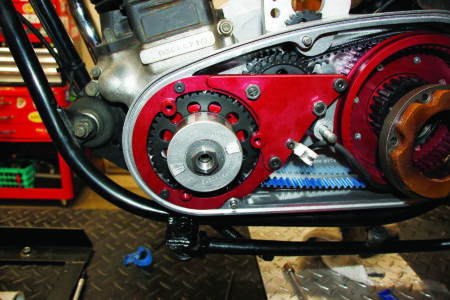
18. Insert the woodruff key for the alternator rotor and fit the rotor on the end of the crankshaft. Using the supplied belleville spring washer and nut, tighten the rotor nut until you just flatten out the belleville washer. A strap wrench (not shown) can help hold the rotor while you do this. Also at this time feed the alternator leads through the grommet in the chain case in preparation for reconnecting them to the main harness.
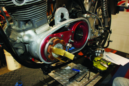
19. Proper gap between rotor and stator is important, I use four brass shims of .008-inch-thickness to help set it. Once you have the gap set all around, tighten up the mounting screws. Then remove one at a time and apply a little blue Loctite to the threads and tighten them.
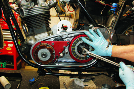
20. Insert the clutch plates, plain and friction, beginning with the extra plain plate supplied. The extra plate increases the stack height, making a much easier clutch pull at the lever. Holding the plates together with your spare hand, tighten the clutch hub nut until you just flatten the supplied belleville washer. Attach the clutch pushrod seal to the exposed threads of the mainshaft, using a small amount of blue Loctite for security. Refit the pressure plate and diaphragm clutch spring.
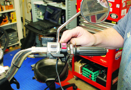
21. A nice combination starter/kill switch comes with the kit, mount it inboard of your throttle and run the wires alongside the existing wires and into the headlight bucket.
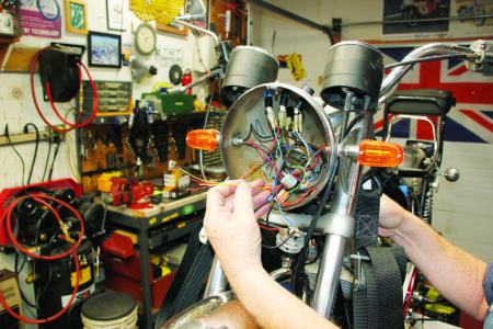
22. Now is the time to lay out the wiring harness supplied with the kit alongside the frame backbone and run the long single wire into the headlight bucket.
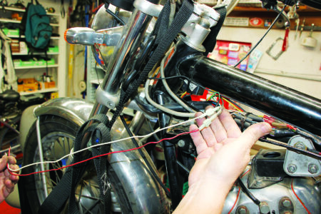
23. For the kill switch, you’ll need to be able to interrupt the power to the ignition. In our case that meant disconnecting the power wires and running long leads from the splice into the headlight bucket where we can connect them to the kill/starter switch.
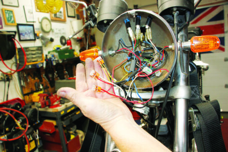
24. Connect the yellow/green wires together with the supplied Wago connectors. Connect one of your ignition power wires to the red lead from the kill switch and connect the other to the red/white wire.
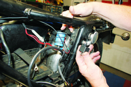
25. Mount the starter relay behind the rear downtube, using the supplied stainless bolt through the lower screw of the side panel mount. This bolt is longer than stock to accommodate the relay bracket. This step can take a little of what the Britishcall “fettling,” it may be easier if you remove the rectifier, mount the relay and then reinstall the rectifier. Connect the wiring harness plug to the relay and route the harness behind the battery carrier.
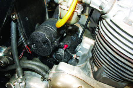
26. Place the starter motor loosely into its place on the inner case, meshing the pinion with the gear, and connect the solenoid wire (red spade connector) and the starter motor connector (ring connector). Tighten the ring connector but don’t overtighten it, you don’t want to spin the wiring stud inside the starter. Route the oil line from the rocker feed. Then fasten the starter to the inner case with the allen bolts and decorative cover supplied.
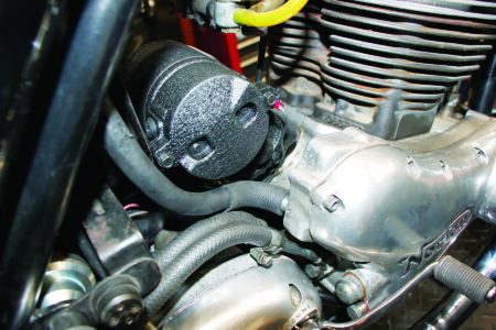
27. Use the shorter breather stub, 90-degree elbow and pipe to connect the timing case breather to the breather hose running to the oil tank.

28. Hook the battery to the main cables, paying careful attention to the polarity of the wires. This one was positive ground, so the thick cable from the back of the primary case went to the positive terminal of the battery. Tickle the carbs, turn on the key, press the starter button and be amazed at how fast it starts.
29. There is one more task to perform and you have to be very careful doing it.
30. There are two screws and locknuts on the alternator carrier. The screws are captive spring balls and they are there to stop the intermediate gear from turning all the time while the engine is running. These have to be adjusted with the engine running, thus the extra care needed. Start with the engine off, back off the locknuts so you can screw in the spring balls. With the engine running, turn both screws in 1/4 turn at a time until the idler gear just stops turning. Stop the engine and use the locknuts to lock the screws and then check your work. That’s it. All done!


